[ad_1]
Per the words of skilled scale modeler Dave Platt, “A scale replica is perpetually a work-in-progress–you simply cease laboring on it.” When I initially test flew my Sopwith Camel with my Zenoah G38 powerplant fully visible in that large radial cowling. Consequently, to enhance its appearance, I have commenced setting up a mock rotary engine. Hopefully, you discover the techniques utilized intriguing as they can be applied to any similar round-nosed aircraft you may be constructing.
Commencing point
Balsa USA serves as an excellent provider for all things WW1 and has been vending quality molded fiberglass mock engines for an extensive period. I obtained a 9-cylinder molding at the recent Rhinebeck Jamboree and promptly prepared it for insertion into the Camel’s engine bay.
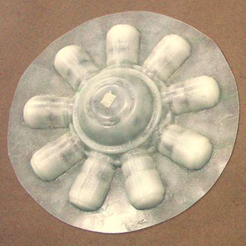
Exquisitely molded from multiple layers of fiberglass cloth, the BUSA molding boasts intricate detailing. Crafting one yourself would demand significantly more time. This image is of an earlier version; the one I acquired recently boasts a sleek gel coat finish on the front.
The primary step with any molded fiberglass piece involves utilizing a grinding wheel and a Moto-tool to eliminate any sharp edges or areas lacking resin. Afterward, submerge it in the kitchen sink and cleanse it with dishwashing detergent to eliminate any residual parting agent potentially remaining on the surfaces.
Displayed here is the open end of the cowling, crucial to utilize a molded engine that fits accurately. The 1/4-scale BUSA rotary engine boasts a diameter of 7 3/4 inches, an ideal match.
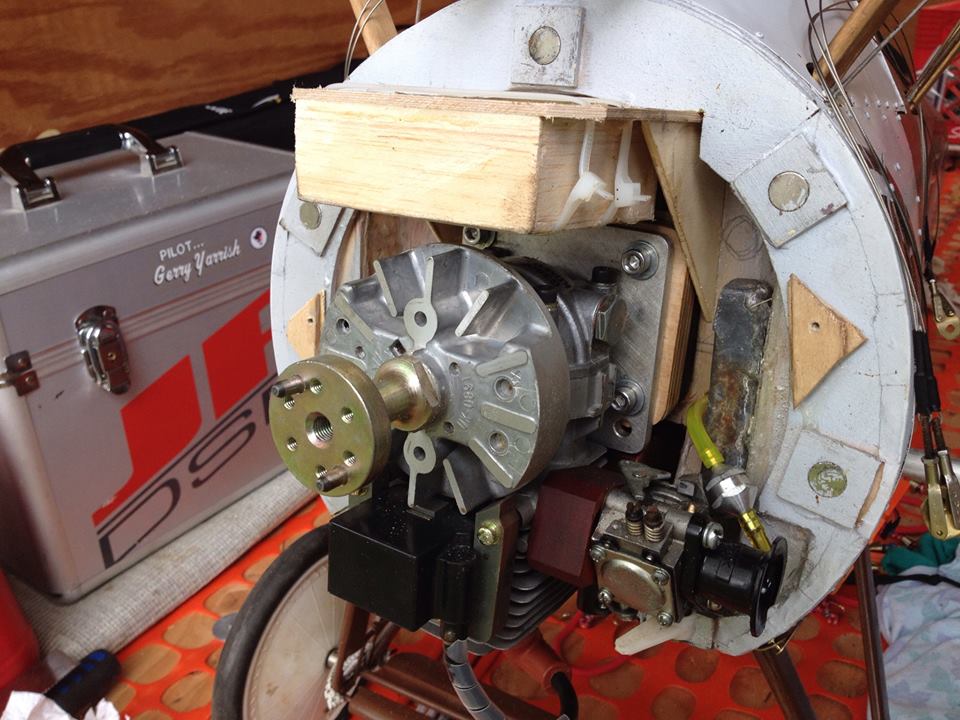
Post removal of the cowling, you’ll observe that I integrated a ballast container filled with lead pellets and resin directly above the engine. I tailored its dimensions with the inclusion of a mock engine in mind.
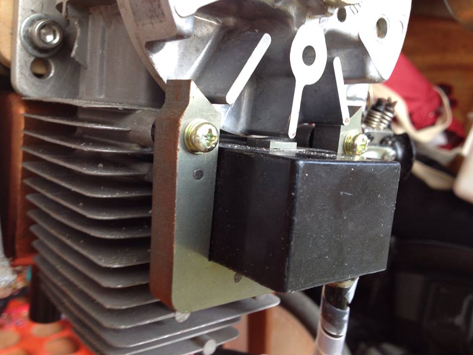
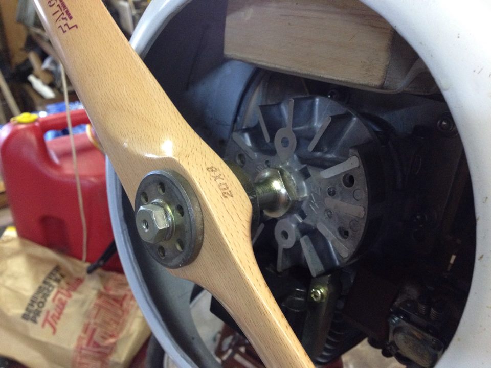
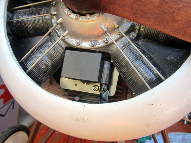
Presented here is the front section of the G38 featuring its flywheel and magneto ignition’s magnet, prominently displayed ahead of the cylinder head. The engine is positioned upside-down with both the cylinder and muffler pointing downwards. The initial task involves enlarging the molded engine to accommodate the ignition block clearance. More significantly, the aperture serves as an inlet for cooling airflow into the engine compartment.
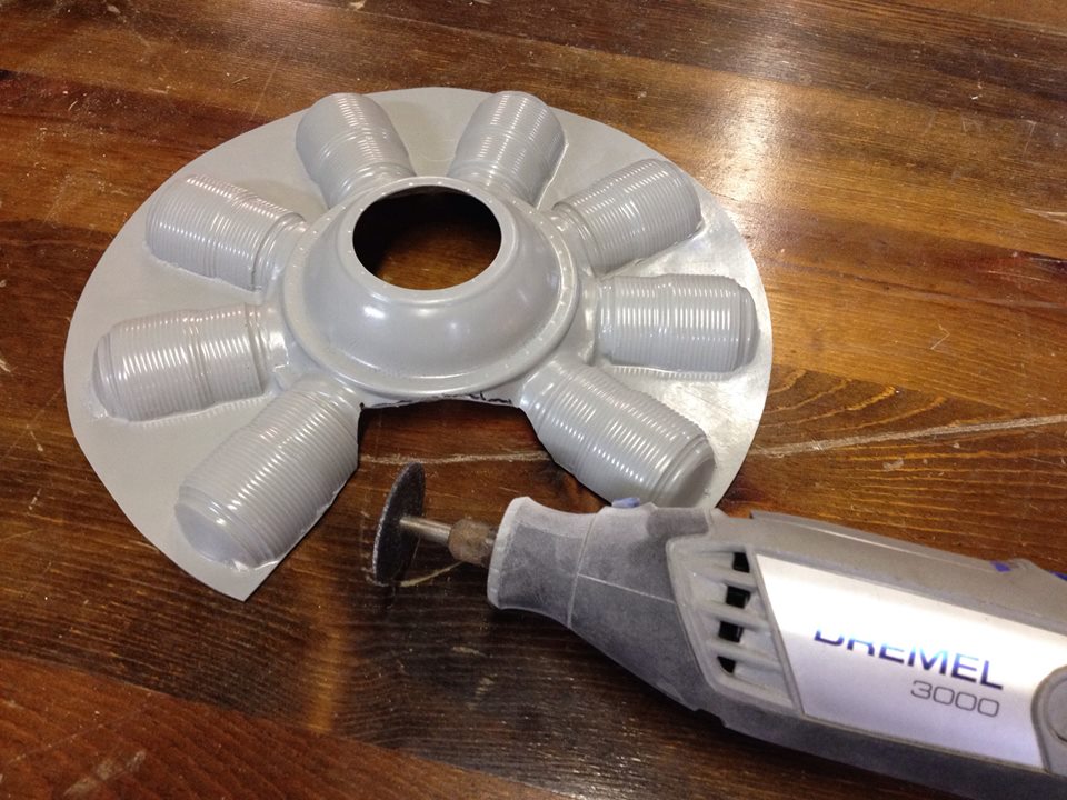
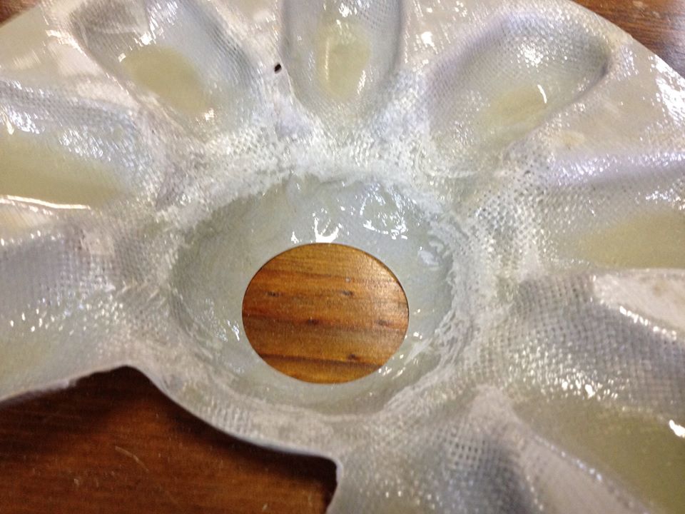
Creating the aperture is a straightforward process with a cutoff disc and a Dremel. I merely eliminated one of the cylinders and widened the area amidst the remaining cylinders as exhibited here. Moreover, the central opening for the crankcase needs to be spacious enough to fit over the G-38’s propeller hub.
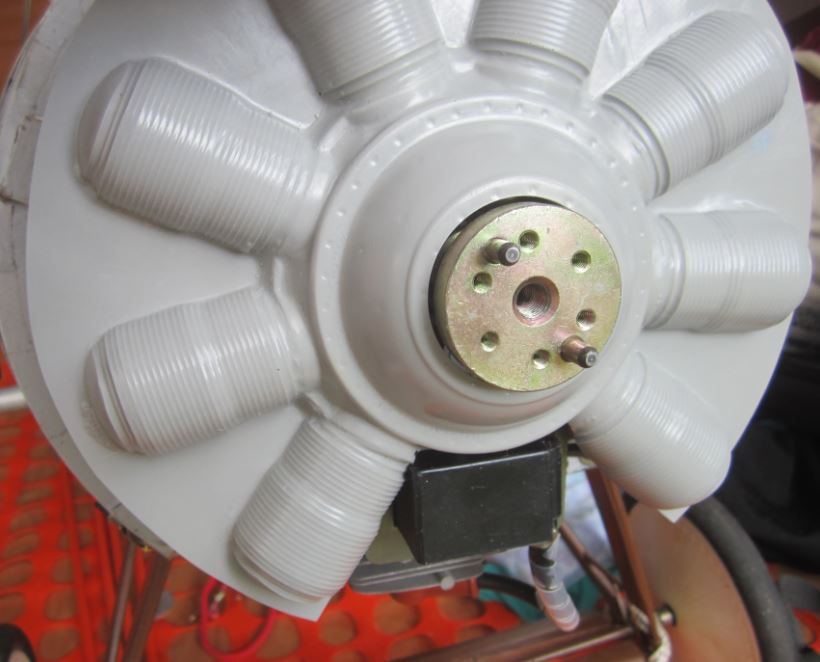
At this juncture, I am fitting the molding over the G-38 for a trial. The opening should ensure approximately 1/8 inch of clearance all around to prevent vibration-induced abrasion of components. Additionally, you can observe that the cylinder directly faces the airflow.
Consequently, the molding aligns impeccably at the center over the G38 while making contact with the front of the ballast container. An added benefit of the box structure is its feature of guiding airflow downward towards and around the engine instead of dispersing upwards in the vacant space surrounding the engine.
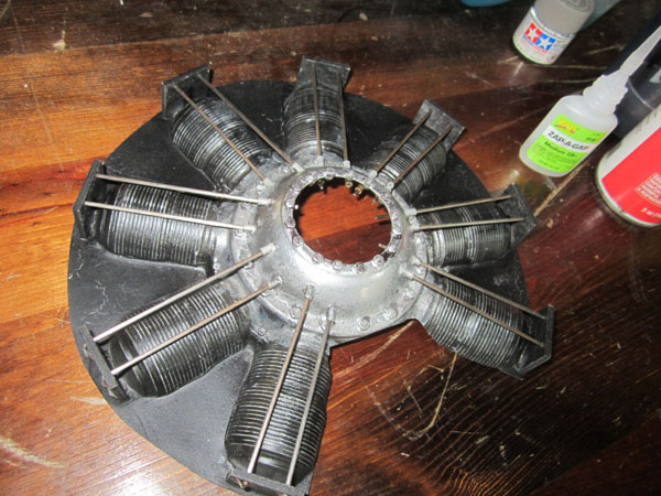
Prior to painting, I drilled apertures and affixed nuts and screws to introduce detailing to the engine case. Additionally, I drilled offset holes in the engine case to insert bushings (derived from short segments of brass tubes) for the pushrods which will be added subsequently. Throughout, I utilize Medium and Thick ZAP CA adhesive. Exercise caution with the accelerator as it may prompt the adhesive to froth up, which isn’t conducive to the finish.
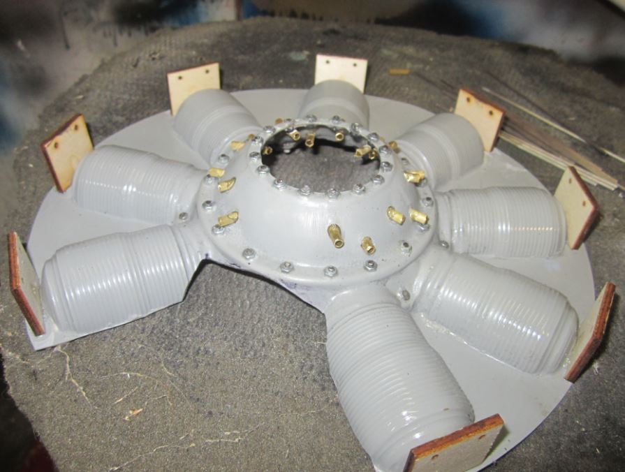
You might have also noticed the lite-ply guides/supports I adhered to the engine molding. These contain 1/16 inch holes set at precise intervals to accommodate the pushrod wires. Below is a basic cutout I loaded into my laser cutter.
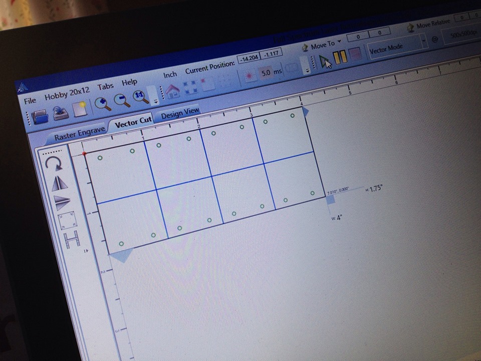
Employing my 40W Full Spectrum Laser Hobby Laser, I managed to import some straightforward CAD designs and cut out the eight pieces requisite for the dummy engine. The lite-ply guide plates are detailed below.
Painting
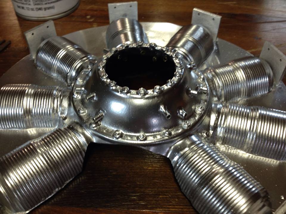
Commencing the paint application, I initiate with a layer of metallic silver from Décor. This paint dries rapidly granting a genuine metallic, almost chrome-like appearance to the component. I favor using this radiant coat as the foundational layer onto which I will apply subsequent weathering layers throughout the procedure.
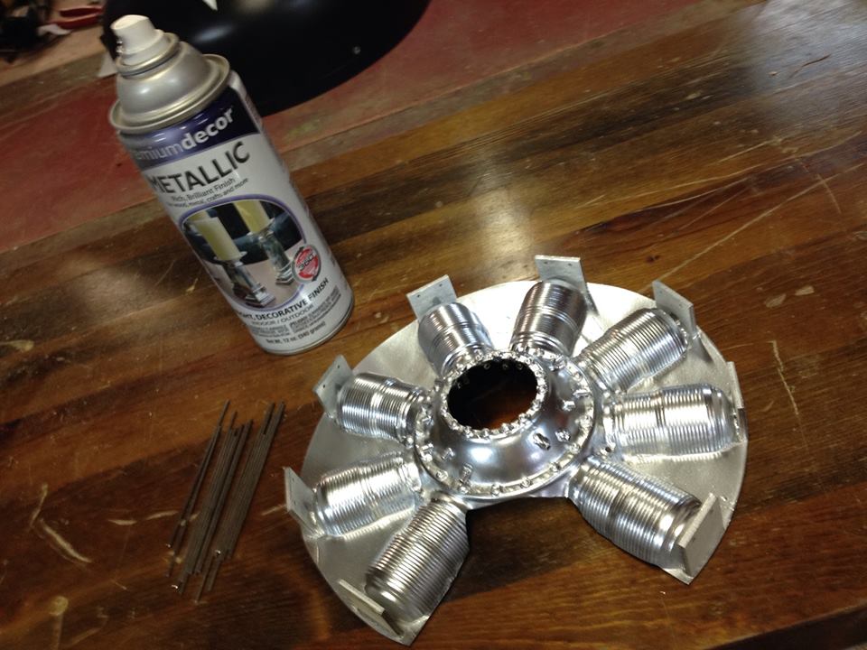
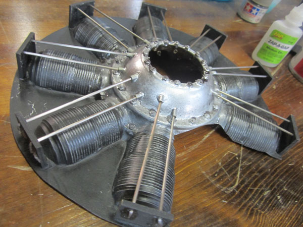
The paint dramatically unifies all components, enhancing the scale likeness. The 16 pushrods are fabricated from sections of 1/16 inch welding wire.
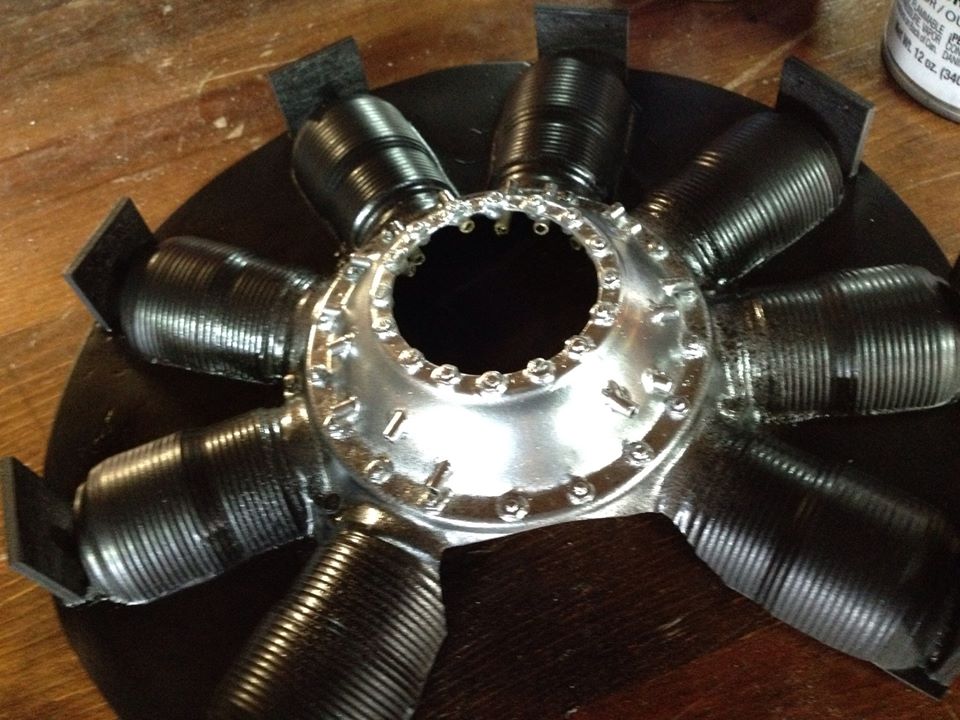
At this juncture, the cylinders and the rear webbing have received a coat of flat black spray paint. I discovered it unnecessary to meticulously mask off the engine case during the cylinder paint application. Once again, I employ Decor spray paint which dries swiftly and remains gas-resistant when dry.
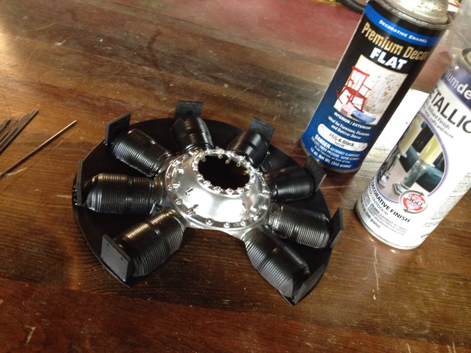
From the image, it’s evident that there is a slight overspray present on the edges of the crankcase, and this is intentional. Additional intricacies and aging effects will be incorporated to enhance the engine’s details and achieve the desired realism for a scale model.
Our next task involves attaching the pushrods. For the Sopwith Camel, I aim for a more weathered appearance.
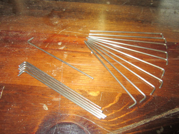
Above, you can observe the 16 pushrod wires crafted for the rotary engine. Using 1/16 inch welding wire, I meticulously sanded them to a polished finish. These wires boast a natural metallic sheen, eliminating the need for painting. Furthermore, one end is bent at a 90-degree angle, with a length of approximately 1/4 inch.

Prior to the pushrod installation, I affixed 320 grit sandpaper to wooden sticks for sanding purposes. Utilizing a wide stick for the upper cylinder and a narrow one for the base, I carefully removed the black paint to reveal the underlying silver and gray shades. This technique adds dimension and reduces the sheen produced by the black paint.
Similar to other aspects of scale modeling and weathering, subtlety is key. Avoid excessive force that may result in widening the silver lines (cooling fin tops).
Following the fin sanding, I carefully applied a thin diluted layer of acrylic black across all details of the engine. Once dry, this black layer enhances the surface details.
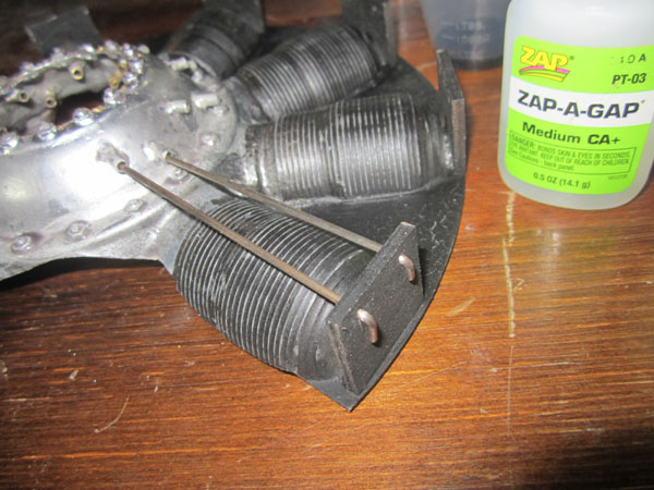
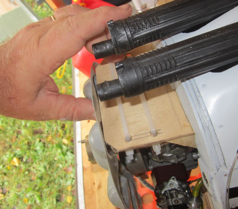
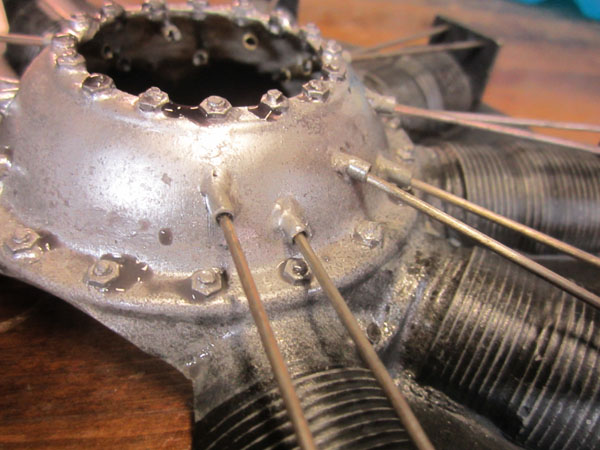
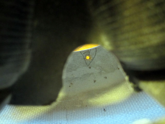
Displayed are two of the inserted pushrod wires positioned within the wood guide plate and brass bushing tubes on the crankcase. A small application of ZAP adhesive secures them in place. These upper plates will remain concealed beneath the engine cowling’s lip.
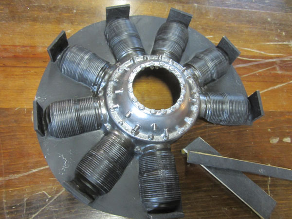
All pushrods are now correctly positioned. They are bonded at the bent ends and within the bushing tubes from the engine molding’s interior.
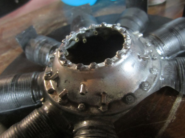
Subsequently, I apply a light mist of pale gray over the chrome silver base color on the crankcase and allow it to dry. I also administer a diluted gray wash using a fine brush on flat surfaces and corners to mimic the accumulation of dust and oil residue typical of a full-size engine.
The gray and black wash remnants are visible around the nuts and screws near the engine and cylinder bases. Allow the washes to dry naturally for the most authentic-looking staining, although the process can be expedited with a heat gun.
The entire project spanned approximately 10 hours distributed across several days, indicating a relatively short timeframe. I ultimately opted to affix the molded engine inside the engine cowling. While this is the conventional method for installation, alternative approaches such as utilizing standoffs around the G38 firewall to mount the dummy rotary engine could also be considered. Below outlines my approach:
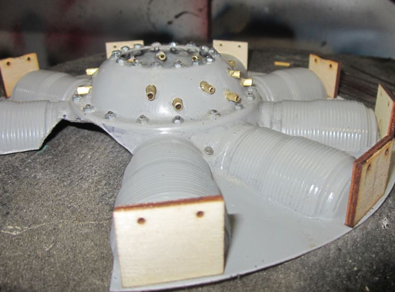
Observe the wooden guide plates positioned above each cylinder. These serve as supports for the pushrod wire ends and provide sturdy attachment points for affixing the molding to the engine cowling’s interior.
Once the glue cures, attach a few more plates inside the cowling. After securing three to four plates, detach the cowling for further work.

A detailed view of one of the plates can be seen in the image above.
Affixed firmly onto the cowling. Proceed with adhering the remaining guide plates in position ensuring to create a robust fillet surrounding the guide plates.

Once all fastening points are secured, remember to create apertures in the webs amidst the cylinders. These are vital for accessing any screws or other attachment points to secure your cowling firmly.
All you require is a hole spacious enough to accommodate a screwdriver. With my cowling secured magnetically, I also affixed two screws to prevent any rotation of the cowling caused by engine vibrations. These screws penetrate through the rear plywood cowling ring and thread into solid points at the front of the firewall.
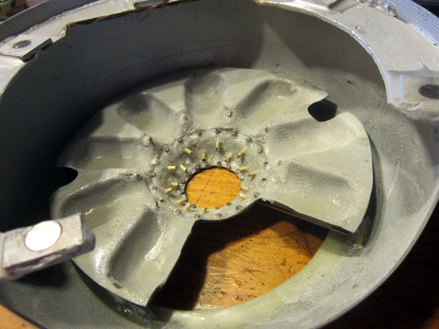
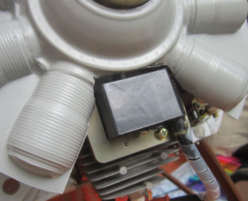
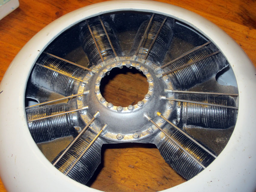
In this image, observe the rear section of the faux engine. Note the ample airflow space around the dummy engine to facilitate engine cooling. The majority of airflow will pass through the sizable aperture just ahead of the cylinder. Furthermore, if there exists a gap between the cowling and any plates (as depicted on the right), fit in a piece of lightweight ply to fill the vacant space. Utilize generous amounts of Zap adhesive along with kicker.
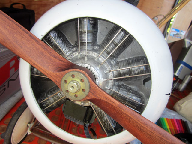
Reinstall the cowling onto the engine and inspect the clearances around the model’s engine. Aim for a minimum of 1/8 inch of clearance all around. Upon achieving proper alignment, temporarily detach the engine once more and apply several light coatings of honey-colored clear Urethane spray finish. This action will seal the wooden guide plates and coat the pushrods to prevent corrosion. Moreover, the color will impart a semi-gloss appearance to the engine, resembling one that has recently run and is coated with castor oil.
TEXT & IMAGES BY GERRY YARRISH
[ad_2]
