[ad_1]
When casual enthusiasts encounter a turbine-powered jet, they observe a jumble of cables and fuel lines scattered around and might think, “Wow! I could never decipher all of that.” In reality, understanding it all is not as complex once you grasp the functions of each component and how they contribute to the overall setup, leading to your jet soaring in the sky. This guide aims to simplify the unique procedures involved in configuring your radio system for operating a gas turbine engine.
Setting up a radio system for a turbine jet is not drastically different from any other model. You must adjust your rates and exponential throw to ensure comfortable flight with your model, whether it is a turbine trainer such as the Turbinator or a large-scale F-18. The key difference in programming a turbine jet lies in configuring the throttle since you no longer have direct control over the throttle as you do with a combustion engine or electric motor.
INTRODUCTORY INSIGHT
Turbine engines are overseen by an Electronic Control Unit (ECU). The ECU serves as the core processor of the operation and is typically housed in a separate unit about the size of a receiver. Connected to the ECU is the ECU battery, which is usually a 3-cell LiFe or LiPo battery supplying power to the fuel pump and starter motor. The ECU also links to the fuel pump control output, a connection to the turbine unit, and a servo link to the throttle channel on the receiver. Additionally, there is a port designated for the Ground Support Unit (GSU), a small screen for monitoring and adjusting turbine settings, and optionally, a telemetry output for relaying data to the radio system, such as turbine status, rpm, voltage, fuel flow, etc.
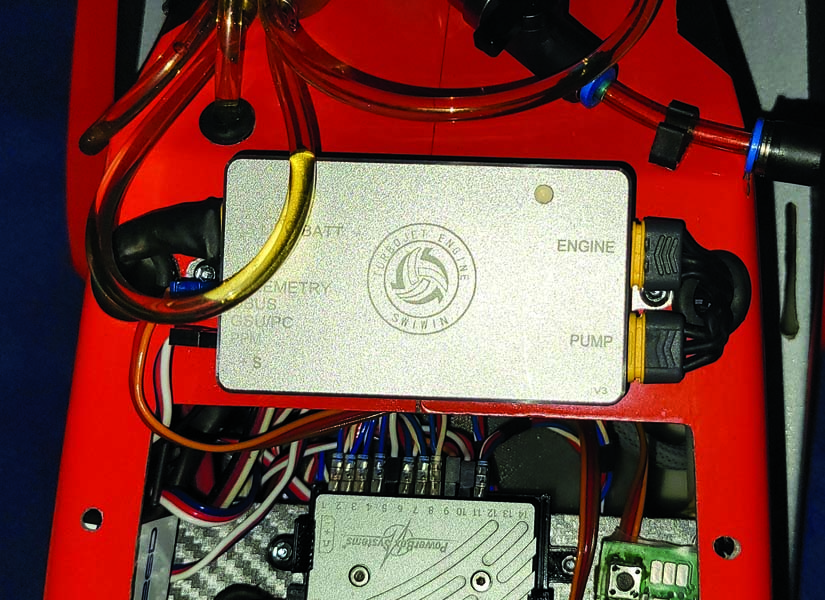
The ECU implemented in my CARF Rebel Hot manages all aspects of the turbine operation, including initiating shutdown in case of signal loss or fuel-related issues.
By regulating the fuel pump, the ECU can incrementally supply fuel to the engine as the throttle stick is pushed forward and decrease it as the throttle is pulled back. This meticulous control is maintained by the ECU through settings like acceleration delay and deceleration delay. If the throttle stick were rapidly pushed forward with the pump voltage in direct alignment, there would be a risk of flooding the engine with excessive fuel, potentially extinguishing the flame and drowning the engine. Similarly, if the fuel supply was reduced too abruptly with immediate pump response, it could starve the engine of fuel, resulting in engine shutdown. Given the undesirable nature of forced landings with a turbine jet, most pilots prefer allowing the ECU to regulate the fuel flow into the engine.
CONFIGURATION OF THE RADIO SYSTEM
In my experience with various turbine engines, including Jet Cat, Kingtech, Swiwin, and Jet Central, a common procedure is necessary, often referred to as “Learn RC.” The ECU requires calibration for three significant points concerning the radio system: Full Throttle, Idle, and Turbine Shutoff. Pilots familiar with calibrating speed controls for electric ducted fan models will find parallels in this process, albeit with additional parameters.
These three points are determined by a combination of throttle stick positioning and throttle trim adjustment. The shutoff point corresponds to a low throttle stick position and full down trim. Idle settings involve a full down stick position with the throttle trim advanced to the maximum level. Full throttle, naturally, requires pushing the throttle stick to its uppermost position. In most radio systems, the default setting for the throttle trim only influences the lower range of throttle stick movement and has no impact on settings beyond half throttle. Certain radios may require configuring this limitation in the trim setup screen; refer to your documentation and servo monitor for guidance.
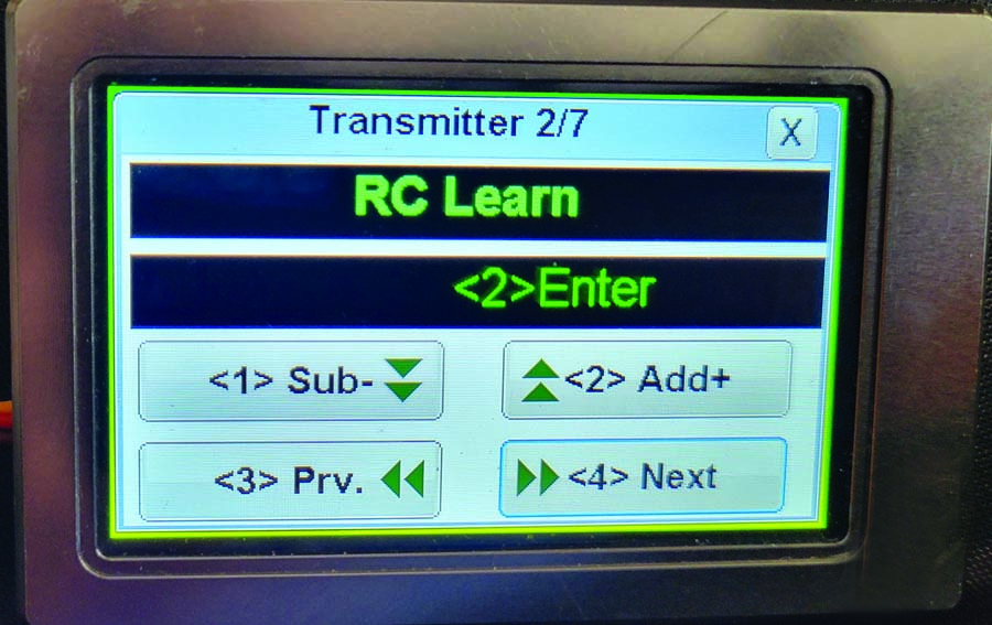
All turbine engines require a specific calibration sequence to synchronize the ECU with the throttle channel on your particular radio system. Pictured here is a Kingtech touch screen GSU.
Activating the Learn RC function on the GSU prompts the system to seek the three designated points. At each point, the system measures the pulse width of the throttle signal, and when the desired stick/trim configuration is achieved, the user presses a button to save the setting and proceed.
Seems straightforward, right? It is indeed, but there are advanced features in our radios that can streamline our tasks. More details on that will be explored later.
PREFLIGHT PROCEDURES
With the throttle and trim set to the lowest positions, the GSU or telemetry unit should display the turbine’s Shutoff status. Advancing the trim to its maximum position should transition the status to READY, indicating that the engine is poised for start-up. Pushing the throttle stick to full for a brief moment and returning it to idle instructs the ECU to commence the starting sequence.
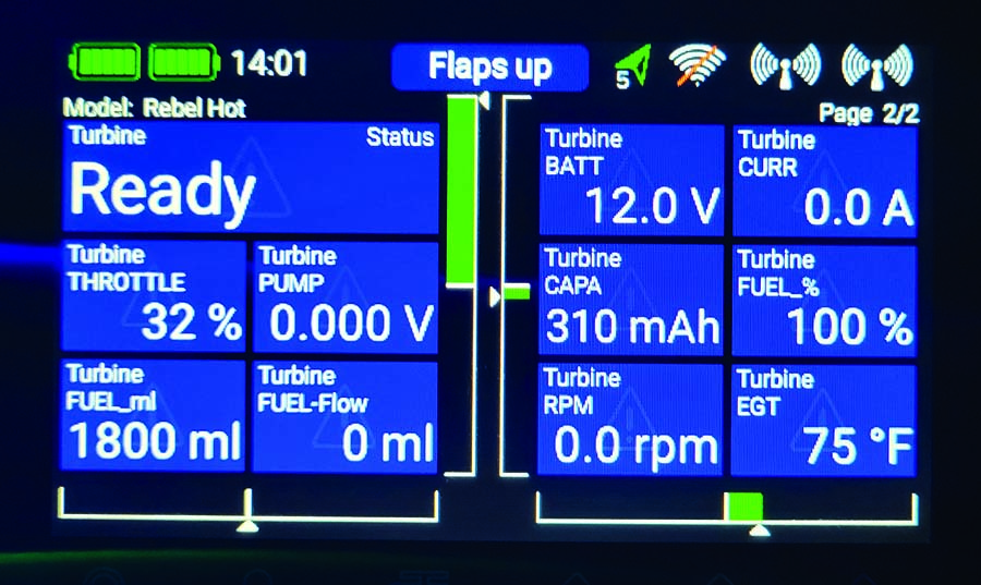
VSpeak module telemetry transmits data that would typically be shown on the GSU to a range of radio systems. The example here displays data from Swiwin turbines on my PowerBox Core radio.
Subsequently, the GSU assumes control of the startup procedure, including engine spin-up, igniting the glow plug or ignitor, adjusting the fuel pump voltage, and verifying specific temperature and rpm thresholds in successive stages. Importantly, users can interrupt the startup process at any time by resetting the trim to the lowest position, halting the fuel supply. If the ECU detects anomalies like ignition failure, low rpm, excessive exhaust gas temperature, fuel supply issues, or deviations from the startup parameters, it will promptly terminate the process and display an error code to explain the interruption. (Technical note: while we’ve covered a general startup sequence, some turbine models may have unique procedures, so always refer to and adhere to the manufacturer’s instructions.)
If the startup progresses as expected, the status will shift to Running, and control over the throttle will be restored to the user. While the engine is operational and the throttle stick is active, it’s crucial to remember that your stick inputs are requesting a specific power output from the ECU, which in turn regulates the necessary fuel flow to meet your requirements by adjusting the pump voltage accordingly.
Keeping an eye on the revolutions per minute and temperature while making small adjustments as necessary.
Enhanced Coding
Now that we have covered the fundamentals, it’s time to recognize that jet aviators often exhibit advanced skills in radio usage, aiming to maximize our utility. The primary advanced configuration we must address is the throttle trimming increment. Most digital radios offer the flexibility to fine-tune how extensive or precise the trims impact the different control surfaces. My Spektrum NX10 defaults to a trim increment of 5 (ranging from 0 to 10), requiring approximately 50 trim clicks to transition from Off to Ready (even when holding the trim button, there is still a slight delay in going from low to high trim). By increasing the trim increment to 10, the transition takes roughly 20 clicks. A more efficient approach involves selecting the Trim Type and configuring it as a two- or three-position switch. Consequently, to engage the turbine, I only need to make one click (for a two-position) or, as I prefer, two clicks (for a three-position) to switch from Off to Ready.
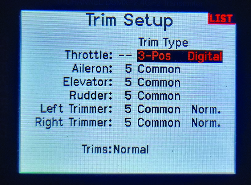
The Spektrum AirWare indicates that you can configure your trim step in various ways, such as converting it into a 2- or 3-position switch for swift turbine activation and deactivation.
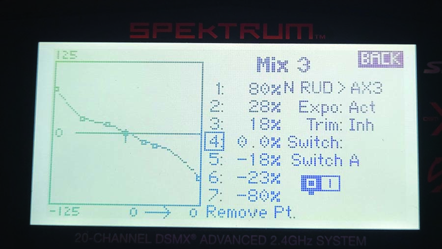
A specialized mix for nose wheel steering is established, preventing steering during gear retraction, allowing independent throw and expo settings from the rudder, and enabling on-the-fly adjustments.
Implementing the two-click technique offers numerous benefits. It enables nearly instantaneous motor activation and, more importantly, immediate deactivation. Conversely, the three-position method delivers almost instant command while providing a single-click buffer, preventing accidental directional activations – representing a balanced approach that I advocate when training inexperienced turbine pilots. An alternative approach is available on certain radios, permitting the removal of the throttle trim from the trim tab entirely and assigning it to a toggle switch. This assignment of trim to a toggle is a common tactic among turbine helicopter pilots.
The crucial aspect is to identify the most suitable method for your operations since swiftly shutting down the turbine in case of an emergency or potential crash, without fumbling on the radio, can prevent substantial damage and financial loss.
NOSE-WHEEL STEERING
Most jet aircraft share a common trait – a steerable and retractable nose wheel. Allow me to unveil a strategy that provides you with independent control of your nosewheel steering, distinct from the rudder, allowing for seamless trimming without menu navigation. Although diverse terminologies may be employed, various radios offer a comparable utility. I will outline the process using the widely-used Spektrum radios, but it can be adapted to radios from diverse manufacturers.
To begin, establish a blend from the rudder channel to the nose wheel steering servo. There exist linear or 1-to-1 blends and curve blends. I opt for a curve blend and utilize the points on the curve to regulate the expo on the nose steering, which can significantly enhance performance. Set the blend to activate via a switch and designate the gear switch for this purpose, ensuring that the steering is operational when the gear is extended. This aligns the steering, deactivates the servo while retracting the gear, conserving the receiver battery from futile servo movements during flight, and prevents potential mechanical damage by steadying the nose wheel within the landing gear well.
Lastly, link the input for the steering servo to LTRM or RTRM, the underutilized minor trimmers on the transmitter’s interface. This step empowers you to finely regulate the nose wheel steering during ground tests without engaging the transmitter’s programming menu for sub-trim adjustment. Although steering assignment to a rotary knob can function, the knob’s stability might be disrupted during model changes or while handling the transmitter, making it a less optimal solution.
Article & pictures by Andrew Griffith
[ad_2]
