[ad_1]
Around 14-16 years ago, I attempted to convert one of the Nitro MT1s to electric power, but unfortunately, the motor burnt out within 2 minutes of running. The performance was lackluster, and the motor placement was subpar. Despite this setback, the idea of converting a Nitro RS4 to electric lingered in my mind.
After all this time, I have finally devised a feasible method with the right gearing in mind. I decided to utilize the Brama 10b (the worst RC I’ve ever used, by the way) due to its compatible gear ratio with the RS4 MT. This saves me from the hassle of searching for a specific large mod 1 spur gear to prevent motor burnout. Moreover, the gearing ratio closely resembles that of the Tamiya DF-02, known for handling demanding tasks effectively.
With that background out of the way, let’s dive into the process.
To begin, I replaced the spur gear assembly with one from an HPI Brama 10b/E10. To ensure proper spacing for the drive shafts powering the front and rear wheels, I took the spur gear rod from the original MT1 spur gear, placed it in a drill, and inserted it into the center of the Brama 10b spur gear, adjusting it to fit onto the shaft. I used teflon bushings typically used in lieu of bearings in entry-level models to secure the gear on the shaft effectively.
The next step, which was impossible for me 14 years ago, involved designing a plate to attach the Brama 10b’s gearbox onto the MT2’s chassis plate, holding the central spur gear assembly, servo, and battery box in place.
Here is an image showcasing the motor mount, spur gear box, and servo before installation on the vehicle.
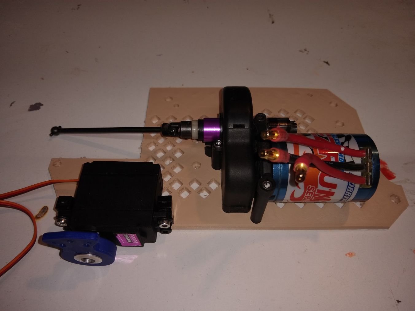
Moving on, let me elaborate on the design process I employed, along with the tools and software used.
I designed the spur gear section of the plate in approximately 20-30 minutes using Tinkercad, taking measurements with calipers and plotting it out. A test print of the spur gear section was conducted to ensure a proper fit. By utilizing this test piece mounted with the spur gear section, I was able to determine an ideal location on the chassis. Subsequently, I measured out the remaining holes based on the initial test pieces’ placement. Faced with difficulties due to the holes not being on a convenient plane, I decided to simplify the process by taking photos of the plate with the test piece taped in place and transferring the data to a graphics editor on my phone.
I added a transparent layer on top of the image, pinpointing the hole centers with the paint tool. This edited image was loaded into Inkscape for accurate hole tracing, then exported to SVG format and imported into Tinkercad alongside the existing motor mount section.
This method enabled me to scale the model based on the mount I had created, streamlining the hole placement process. While it seems complex when written down in a simplified manner, the actual workflow felt more intuitive in practice.
[ad_2]
